)
Turning on the lights used to require a walk to the wall switch; nowadays, various smart devices exist to relieve you of that inconvenience. In this post I make such a device, but avoid putting a HTTP server on it. Read on to see how and why.
So this is how I control the lights in my room
$ which lights
lights () {
  echo L$1 |
  socat -t2 - 'SOCKET-CONNECT:31:3:x5a476abf713cx0100,bind=x0671da7d1a00x0100'
}
This is a shell function for any POSIX-compatible shell (like bash or zsh). It’s invoked on the command line like a regular command or alias, with a single argument, which gets prepended with L and piped into some arcane command. On the first try after rebooting my PC it takes a little longer, but it’s reasonably fast. I don’t have it bound to a keyboard shortcut only because it’s used fairly infrequently.
In this post I’ll document what makes it tick blink, working through its internals at every stage.
A rather dim bulb
What this command toggles is not a smart bulb by any means. Not one of these cheap Chinese bulbs, which sometimes actually contain an ESP32 chip and add yet more noise to your already overcrowded WiFi network. Nor is it a more modern, ZigBee-enabled one, like IKEA Trådfri or Philips Hue. No – it’s a plain, E14-size LED bulb (actually two of them in a single fixture).
However, that fixture is a combo ceiling-fan-plus-light – one controlled with an IR remote. So it stands to reason that I also have a similar function to control the fan speed – it’s nigh identical, omitting the L prefix.
Invisible light
However, it’s not just a command that drives some sort of an infrared dongle – these are all but nonexistent nowadays. Back in the age before smartphones and 4G, infrared was a very popular (if not very fast) way to exchange data between handsets. Many could also be used as TV remotes with a certain application. Later on, some smartphones used to ship with an IR diode, called a blaster. Major brands have mostly abandoned this technology, but some are still available in 2021.
But we’re talking about a Linux PC, not a smartphone. USB variants of these blasters are practically extinct. Searching for them on a popular Chinese market site mostly yields infrared extenders, which often come with a USB connector but only for the sweet +5V juice, and are completely useless for the task; or tiny USB-C blasters which you can use with your smartphone (again) and an ugly app. Alternatively, you can get IR hubs, which need to be placed in sight of the receiving device, and usually work over your home WiFi network, with yet another ugly app or at least your chosen home automation solution.
Spotlight on: microcontrollers
Therefore, I need to cobble up a solution on my own. Fortunately, amateur electronics hackers like me have never had it easier: I can order some infrared LEDs, any one of a hundred tiny single-board microcontrollers, wire them up together, and voilá! lights on. Turns out, I didn’t even have to do that part. Rebased’s own Tomek Stachewicz, a more experienced hardware tinkerer, provided me with one, which he used for a similar purpose. It’s basically three IR LEDs plus appropriate resistors, connected through a transistor to an ESP32 chip’s GPIO line.
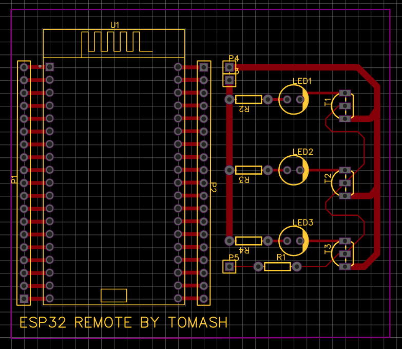 Connect P3 and P4 to +3V and GND, respectively, and P5 to a digital GPIO pin on the ESP32.
EasyEDA files and BOM available on GitHub.
Connect P3 and P4 to +3V and GND, respectively, and P5 to a digital GPIO pin on the ESP32.
EasyEDA files and BOM available on GitHub.
Blinking rapidly
Sending IR signals to devices is just the hard version of Arduino’s basic Blink sketch. The difference is that we need to blink it very, very fast. How fast? Many devices – including Sony, Samsung, LG, Toshiba and my brand of ceiling fan/light – use the 38 kHz carrier frequency1, which means that we blink 38,000 times per second, or about once every 26.5 microseconds. If the LED stays on for 13 of these 26 µs, we call this a 50% duty cycle, which most remote specs recommend. This frequency must match what the IR receiver is tuned for.
Next, the carrier needs to be turned on and off at specific intervals. Bits are sent by first keeping the carrier on for specified time, then off. For example, a Sony-flavor 1 bit is sent by keeping the carrier on for 1200µs, then off for 600. A 0 bit is on for 600, off for 600. For Panasonic, that would be 432,1296 for a one, and 432,432 for a zero. Philips’ RC6 protocol uses a fatter fourth bit (double the duration of other bits) and Manchester encoding with equal intervals instead.
The whole sequence is prepended by a header mark, which is also an on-off sequence, but with times that are a multiple of these used for data. Panasonic’s header is 3456,1728: eight lengths then four lengths (of a 432 base interval). Some protocols also use a footer mark sequence. Then there’s a set gap time, and zero or more repetitions of the entire message.
Green light: into the code
All of these complicated timings are, however, nicely abstracted by IRremoteESP8266. Despite being named after another chip, it’s also useful on the ESP32. It turns out that my fan is driven by the Symphony protocol.
const uint16_t kIrLed = 15; // LEDs connected to this pin
IRsend transmitter(kIrLed);

void setLights(uint8_t onoff) {
  const uint16_t codes[2] = {0xC20, 0xC08};
  Serial.printf("Setting lights to %d with code %x\r\n",
                onoff, codes[onoff]);
  // message is 12 bits long (see below) and sent three times total
  transmitter.sendSymphony(codes[onoff], 12, 2);
  delay(100);
}
To discover which codes actually drive my light, I used trial and error. IRremoteESP8266 code links to the datasheet for SM5021B, an encoder chip used in the remote. Its protocol has only eight different messages, but each can contain two custom code bits. So the total number of legal codes is just 32. But then my remote has only six buttons, which made the search brief.
> 0xc20.to_s(2)
=> "110000100000"
# 1 1 0 | 0 0 | 0 1 0 0 0 0 0
# ^       ^     ^ 0100000 is code K6
# |       + custom code bits
# + start word, always 1 1 0
Code for setting fan speed is very similar, with a longer lookup table. For testing, I plugged the board into USB and used its builtin UART-to-USB serial converter.
void setup() {
  Serial.begin(115200);
  transmitter.begin();
}

void loop() {
  // Do nothing while serial is not connected
  if (!Serial.available()) {
    delay(1000);
    return;
  }

  String command;
  command = Serial.readString();
  // Removes any whitespace, in-place
  command.trim();

  if (command == "0" || command == "1" || command == "2" || command == "3") {
    setFanSpeed(command[0] - '0');
  } else if (command == "L1" || command == "L0") {
    setLights(command[1] - '0');
  }
}
Connected, lights on
At this point, I could already set up shell functions to work in this wired mode.
lights() {
  echo L$1 |
  socat -t2 - file:/dev/ttyUSB0,b115200
}
The next step was to make this work untethered, without wires (except power, obviously).
Bringing into the light: socat
This tool, a venerable old piece of software, creates a data connection between two bidirectional streams. It’s like a shell pipe, but works in both directions, and is not restricted to only processes and files. It can be used to bridge a serial-only device to the network, function as an SSL-terminating proxy, IPv6-to-IPv4 tunnel, it can expose a CLI program to the network, stream logs over UDP, and do many other things. It’s the universal connector for everything.
In the function above, socat is joining stdin/stdout - to a named character device which must already exist FILE:/dev/ttyUSB0. The device is supplied with extra options after the comma: serial line speed b115200 matching what was set in setup(). Next, we echo a command into this pipe. The microcontroller code receives it in loop(), and engages the infrared LEDs.
Action at a distance
Let’s look at the magical command again:
lights () {
  echo L$1 |
  socat -t2 - 'SOCKET-CONNECT:31:3:x5a476abf713cx0100,bind=x0671da7d1a00x0100'
}
The stdin/stdout part we already know. Let’s look at the other end of the connection. The manpage explains:
SOCKET-CONNECT:<domain>:<protocol>:<remote-address>
Creates a stream socket using the first and second given socket parameters and SOCK_STREAM (see man socket(2)) and connects to the remote-address. The two socket parameters have to be specified by int numbers. Consult your OS documentation and include files to find the appropriate values.
This matches the socket() syscall, basically. The domain parameter is alternatively known as the protocol family, or address family. These are defined in <sys/socket.h>, canonically located at /usr/include/sys/socket.h. That file contains mostly function prototypes, but it does include <bits/socket.h>, where we find, among others:
#define PF_INET 2 /* IP protocol family. */
#define PF_BLUETOOTH 31 /* Bluetooth sockets */
// Followed by mapping of AF_ names to PF_ equivalents
Now, this was a moment of discovery for me. Previously, I assumed the only way to work with Bluetooth is to select one of its myriad of protocols and follow its sad, committee-driven, over-engineered design. For this kind of device, I’d probably use the most generic ATT profile, map the commands to attributes, and react when they are set appropriately2. But from now on, I could treat Bluetooth as just another network protocol, on a completely isolated network, with its own quirks and requirements.
What about the 3? This is the third parameter to socket(), which is the protocol. Every address family has at least one protocol supported. For TCP/IP, it corresponds to the protocol field in the packet header (e.g. 2 is ICMP). And for Bluetooth, it selects a specific protocol. These are defined in <bluetooth/bluetooth.h>:
#define BTPROTO_L2CAP   0
#define BTPROTO_HCI     1
#define BTPROTO_SCO     2
#define BTPROTO_RFCOMM  3
#define BTPROTO_BNEP    4
#define BTPROTO_CMTP    5
#define BTPROTO_HIDP    6
#define BTPROTO_AVDTP   7
Number 3 is RFCOMM, which is the serial port emulation layer. ESP32 supports Bluetooth (as well as WiFi), and the toolchain I used has built-in libraries for that. Using RFCOMM is similar to using the UART: a BluetoothSerial class is available, which can be used for reading or sending text. Let’s add support:
BluetoothSerial SerialBT;
void setup() {
  transmitter.begin();
  Serial.begin(115200);
  SerialBT.begin("FanSerial"); // Advertised device string
}
Let’s accept commands from RFCOMM as well:
void loop() {
  if (!Serial.available() && !SerialBT.available()) {
    delay(1000);
    return;
  }

  String command;
  if (Serial.available())
    command = Serial.readString();
  else if (SerialBT.available())
    command = SerialBT.readString();

  command.trim();

  if (command == "0" || command == "1" || command == "2" || command == "3") {
    setFanSpeed(command[0] - '0');
  } else if (command == "L1" || command == "L0") {
    setLights(command[1] - '0');
  }
}
Now, how do we specify the Bluetooth device to connect to? Enter the third argument to SOCKET-CONNECT: the remote address. To the manual once again:
The remote-address must be the data representation of a sockaddr structure without sa_family and (BSD) sa_len components.
What constitutes “data representation” isn’t explained well, but we can get a glimpse in the socat manual’s examples section, where SOCKET-DATAGRAM is used. It appears to be a hex representation of the structure, with fields separated by x. For Bluetooth, and specifically RFCOMM, the structure we need is sockaddr_rc defined in <bluetooth/rfcomm.h>:
/* RFCOMM socket address */
struct sockaddr_rc {
        sa_family_t     rc_family;
        bdaddr_t        rc_bdaddr;
        uint8_t         rc_channel;
};
The manual tells us explicitly to skip the family field, so we need to specify only the Bluetooth Device address bdaddr and channel. The latter is like a TCP port number. ESP32’s BluetoothSerial uses channel number 1. Now, what’s bdaddr_t?
/* BD Address */
typedef struct {
    uint8_t b[6];
} __attribute__((packed)) bdaddr_t;
It’s just six bytes of the Bluetooth MAC address of the device. Backwards, because that’s how strtoba() converts a textual colon-separated one.
SOCKET-CONNECT:31:3:x5a476abf713cx0100,bind=x0671da7d1a00x0100
#              ^  ^  ^           ^           ^ HCI (Bluetooth host) address and channel
#              |  |  |           + channel 1
#              |  |  + Device address: 3c:71:bf:6a:47:5a
#              |  + BTPROTO_RFCOMM
#              + AF_BLUETOOTH
When writing this post, I discovered that the command works just fine with bind address removed. Also, despite being a single byte in the structure, socat insists on using an additional byte after the channel number, which you see above as x0100 and not just x01. I am not sure why, maybe it has to do with padding and/or alignment issues.
Now, why didn’t I just use HTTP for all this
Most similar projects would not delve into Bluetooth, and instead just slap an HTTP server on this and call it done. In fact, this is how Tomasz implemented his solution on the very same board. While his is written for the Arduino IDE and mine is a PlatformIO project, it was where I learned about the infrared library IRremoteESP8266.
One reason not to do an HTTP server, is that this microcontroller now doesn’t need to run a TCP stack. It doesn’t need an address allocation by my router. It’s no longer an insecure IoT device, as it cannot access my network.
Also, I now don’t need to worry if the page served is nice or ugly, or if I designed the API correctly. I have a CLI that uses bog-standard tools, and literally can’t be used for anything else. It has exactly the six commands it needs, and nothing else.
Security model
You may observe that this connection code does no verification of who is actually connecting. Meaning that, after reading this article, my neighbors could connect and annoy me by blinking the lights in my room. And that is fully correct. While I did change the MAC addresses used in all examples, the code actually running is identical. So why not secure it further?
- Bluetooth’s range, and the number of walls it needs to cross to reach my device. Whereas I connect it usually from a couple of meters away.
- No access to other resources beyond my light and fan. Damage potential is minimal. Also, I can just turn it off using a wall switch, preventing all attacks.
- No need to store any permanent data (paired devices list) on the device. Vastly simpler implementation.
- Even without Bluetooth: someone could rig a bank of super-bright IR leds and blast at me from a window across the street, with the same effect.
None of these are real threats, or offer advantage to the attacker.
Full source code is available on my GitLab. Board schematics and BOM on Tomasz’s GitHub.
-
Why is it exactly 38 kHz? Because in the 1980s, ceramic resonators of exactly 432 kHz needed to achieve 36 kHz were not easily available. But other values nearby – like 455 kHz and 429 kHz – were, due to their use in commercial AM radio. These yielded carrier frequencies of 37.92 kHz and 35.75 kHz, close enough to 38 and 36 kHz, respectively. Read more on Wikipedia. ↩
-
And if I wanted to use Bluetooth Low-Energy, this would likely have been the only way. ↩